What Factors Should You Consider When Selecting Pushbutton with Indicator Light?
The control panel of a modern industrial machine is a symphony of inputs and outputs. Among the most critical elements are the humble pushbuttons with indicator lights—the primary interface between human operators and complex machinery. Each button carries immense responsibility: starting a conveyor, stopping a high-speed rotor, or signaling an emergency shutdown. A single mis-specified button can lead to operator confusion, equipment damage, or even life-threatening accidents. In a bustling manufacturing facility, a machine operator once pressed a green pushbutton with indicator light, expecting it to start the equipment. Instead, it initiated an emergency stop sequence. The button's indicator light had been wired in reverse polarity—green, which universally means "go," was actually signaling "stop." This simple oversight caused hours of downtime and an investigation that could have been avoided with proper selection and wiring verification. This scenario underscores a critical reality: selecting the right Pushbutton with Indicator Light is not a trivial procurement decision; it is a fundamental engineering task that demands a systematic evaluation of multiple interdependent factors.
When selecting a Pushbutton with Indicator Light, engineers must navigate a complex decision matrix that spans electrical compatibility, environmental resilience, mechanical longevity, visual signaling requirements, and physical installation constraints. The process begins with understanding the application's electrical demands: voltage, current, and contact configuration. It extends to the environment where the button will operate—whether it is a clean control room, a dusty factory floor, or a wet outdoor installation. Mechanical life expectancy and tactile feedback determine operator satisfaction and long-term reliability. The color and mode of the indicator light must conform to international standards to ensure immediate, intuitive understanding. Finally, physical dimensions and mounting options must align with panel cutouts and design aesthetics. At Yueqing Gongtong Electric Co., Ltd., our factory has manufactured millions of Pushbutton with Indicator Light units, and we have seen how a seemingly minor specification can make the difference between decades of reliable service and premature failure. This comprehensive guide will walk you through each critical factor, providing the technical insights needed to make an informed decision.
Table of Contents
- 1. What Is a Pushbutton with Indicator Light and Where Is It Used?
- 2. What Electrical Specifications Must You Evaluate?
- 3. How Do Environmental Conditions Affect Pushbutton Selection?
- 4. What Mechanical and Durability Factors Matter?
- 5. How to Choose Between Different Indicator Light Colors and Modes?
- 6. Frequently Asked Questions (FAQ)
- 7. About Yueqing Gongtong Electric Co., Ltd.
- 8. Conclusion
1. What Is a Pushbutton with Indicator Light and Where Is It Used?
1.1 Definition and Basic Structure
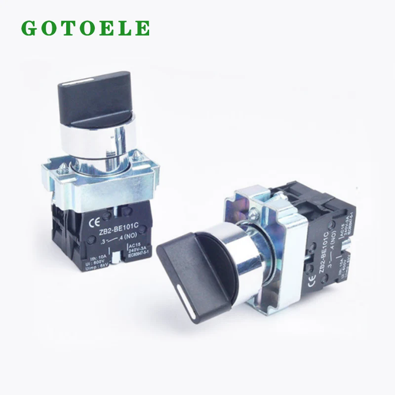
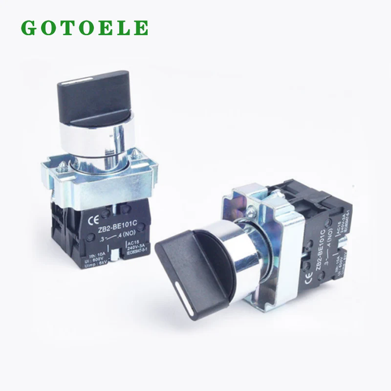
A Pushbutton with Indicator Light is an integrated electromechanical control device that combines two essential functions into a single, compact unit: a manual switching mechanism (the pushbutton) and a visual status indication (the indicator light). When an operator presses the button, the internal contact mechanism opens or closes an electrical circuit, controlling a process or piece of equipment. Simultaneously, the built-in indicator light provides immediate visual feedback, confirming the button's actuation or communicating the status of the controlled system. This dual functionality—combining human input with machine output—makes the Pushbutton with Indicator Light an indispensable component in virtually every control panel across industries.
To understand how a Pushbutton with Indicator Light functions, we must examine its internal anatomy. The device consists of four primary structural elements working in coordination:
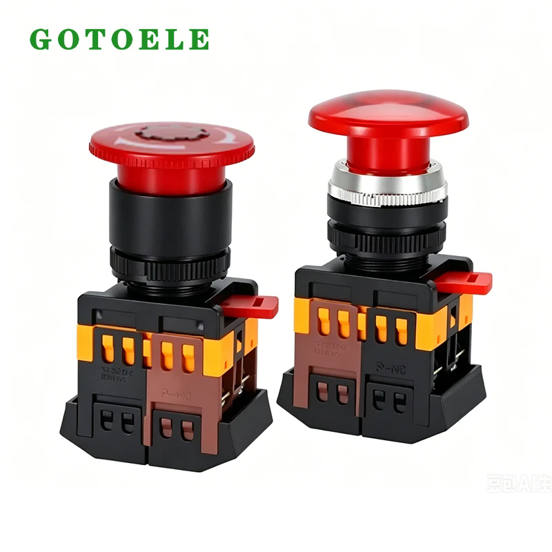
1. Operating Head (Button Cap). This is the physical interface that the operator contacts. It is typically made from engineering plastics (such as polycarbonate, ABS, or nylon) or metal (aluminum, stainless steel, or brass). The operating head is available in various shapes: flat or flush-mounted (recessed to prevent accidental actuation), raised or convex (easy to locate and press), and mushroom-head (designed for emergency stop applications, providing a large, easily grab-able surface). The cap often features a transparent or translucent section that allows the indicator light to shine through, creating the illuminated appearance.
2. Indicator Light Source. The illumination is produced by an internal light source. Historically, incandescent lamps were used, but today's Pushbutton with Indicator Light primarily utilizes Light Emitting Diodes (LEDs), which offer superior longevity, lower power consumption, and brighter, more vivid colors. The LED can be designed to provide different colors (red, green, yellow, blue, white) and different modes (steady on, flashing, or blinking). The light is diffused through the cap or through a separate pilot light lens.
3. Switching Mechanism (Contacts). Beneath the operating head is the contact block. This mechanism translates the mechanical push into an electrical switching action. The contacts are typically made of silver alloy or gold-plated materials to ensure low resistance and reliable operation over millions of cycles. The contact configuration can be momentary (the button returns to its original position when released) or maintained (the button stays in the position to which it is pressed). The contact arrangement includes normally open (NO), normally closed (NC), and combinations thereof, allowing the button to be used in various control logics.
4. Termination and Housing. The rear section of the Pushbutton with Indicator Light provides the electrical connection points (screw terminals, plug-in connections, or PCB pins). The housing, which encapsulates the internal components, is designed to protect against ingress of dust, moisture, and other environmental contaminants. The material and sealing design determine the device's IP (Ingress Protection) rating, a critical specification we will explore later.
The operating principle of a Pushbutton with Indicator Light is straightforward yet elegant. When the operator applies force to the operating head, the mechanical linkage moves the contact block. A spring mechanism provides tactile feedback—a discernible "click" or resistance—informing the operator that actuation has occurred. The contacts then change state, opening or closing the circuit. Simultaneously, the indicator light illuminates (if the circuit is designed to energize the light upon actuation) or changes its status, providing visual confirmation. This dual action—tactile and visual—ensures that the operator receives immediate, unambiguous feedback about their action and the resulting state of the controlled system.
1.2 Types and Application Scenarios
The variety of Pushbutton with Indicator Light products available in the market reflects the diverse demands of modern industrial applications. The selection of a specific type depends on the operating environment, user interface requirements, and the nature of the control system. Understanding this taxonomy is the first step in a successful selection process.
The table below provides a comprehensive classification of Pushbutton with Indicator Light products, organized by key attributes and their application contexts.
| Classification | Sub-Types | Typical Applications |
| By Material | Plastic (ABS, Polycarbonate, Nylon), Metal (Aluminum, Stainless Steel, Brass) | Plastic: Indoor control panels, office equipment, medical devices. Metal: Heavy machinery, outdoor equipment, marine environments, food processing. |
| By Shape | Round, Square, Rectangular | Round: General-purpose, most common. Square: Modern aesthetic panels. Rectangular: Multi-panel clusters, space-efficient designs. |
| By Operating Head | Flush/Flat, Raised/Convex, Mushroom, Key-operated | Flush: Anti-vandal, prevent accidental actuation. Raised: Easy identification, frequent actuation. Mushroom: Emergency stop, large, easily pressable. Key-operated: Security-sensitive applications, restricted access. |
| By Reset Type | Momentary (Spring Return), Maintained (Latching) | Momentary: Start, stop, jog, and other temporary controls. Maintained: On/Off switches, mode selection, and settings that need to hold state. |
| By Protection Rating (IP) | IP40, IP54, IP65, IP67, IP69K | IP40: Control rooms, clean environments. IP54: Dusty but dry areas. IP65: Outdoor, rain and washdown. IP67: Temporary immersion, marine applications. IP69K: High-pressure washdown, food and beverage. |
The application landscape for Pushbutton with Indicator Light is vast and varied. Here are the most common sectors and specific applications:
- Industrial Control Panels: In manufacturing facilities, Pushbutton with Indicator Light are used to start, stop, and monitor machinery such as conveyor belts, CNC machines, packaging equipment, and assembly lines. Here, the combination of an illuminated button provides a clear "running/stopped" status, reducing operator error.
- Construction and Heavy Equipment: In excavators, cranes, and agricultural machinery, Pushbutton with Indicator Light are used for engine start/stop, horn, and lighting controls. These applications demand high durability, sealing against water, and resistance to vibration.
- Elevators and Escalators: The call buttons inside and outside elevators are typically Pushbutton with Indicator Light that illuminate to indicate a call has been registered. This feedback is essential for passenger confidence. The buttons must be robust and have high mechanical life (millions of cycles).
- Medical and Laboratory Equipment: In hospital beds, diagnostic machines, and lab analyzers, Pushbutton with Indicator Light are used for critical functions. These devices often require antimicrobial materials, low noise, and precise tactile feedback to ensure accurate operation in high-stress environments.
- Transportation Infrastructure: Traffic control systems, emergency stop buttons on railway platforms, and pushbuttons at public pedestrian crossings all use Pushbutton with Indicator Light. These outdoor applications demand IP65 or higher sealing, UV resistance, and high visibility.
- HVAC Control Systems: In building management, Pushbutton with Indicator Light control heating, ventilation, and air conditioning units. The indicator light provides confirmation that a fan or pump has been activated, a critical signal for maintenance engineers.
The common thread across all these applications is the reliance on the Pushbutton with Indicator Light to provide both control and feedback. The specific combination of physical robustness, environmental sealing, tactile feel, and visual clarity required varies by industry, but the fundamental principles of selection remain consistent.
2. What Electrical Specifications Must You Evaluate?
The electrical specifications of a Pushbutton with Indicator Light are the most fundamental parameters for compatibility with your control system. A mismatch between the button's ratings and the system's requirements can lead to contact welding, premature failure, or failure to operate. The primary electrical specifications to evaluate are the rated voltage, rated current, contact configuration, and the characteristics of the indicator light. Each parameter interacts with the application's load type, the voltage available, and the control logic.
1. Rated Operating Voltage and Current. The rated voltage is the maximum voltage that can be safely applied across the Pushbutton with Indicator Light's contacts and the indicator light. Rated current is the maximum current the contacts can carry. These ratings are typically provided for both AC and DC circuits, as switching characteristics differ. DC circuits are generally more challenging to break because the current does not have a natural zero-crossing point, which can lead to arcing. For Pushbutton with Indicator Light used in industrial environments, typical voltage ratings are 24V DC, 110V AC, 230V AC, and 400V AC, with current ratings ranging from a few amperes to tens of amperes.
When matching the rated current to your load, consider the load type. Resistive loads (e.g., heaters, incandescent lamps) have an inrush current that is typically 1 to 1.5 times the steady-state current. Inductive loads (e.g., motors, solenoids, relays) can have inrush currents up to 6-8 times the steady-state current, particularly when starting. Capacitive loads (e.g., power supplies) can also have high inrush currents. For a Pushbutton with Indicator Light switching an inductive load, the rating should be de-rated. A general rule is to ensure the rated current of the button is at least 1.5 to 2 times the steady-state current of the load to accommodate the inrush.
2. Contact Configuration and Contact Material. The contact arrangement determines the control logic. The common options include:
- 1NO (One Normally Open). The circuit is open when the button is at rest and closes when pressed. Used for start, activation, or momentary actuation.
- 1NC (One Normally Closed). The circuit is closed when the button is at rest and opens when pressed. Used for stop, deactivation, or safety circuits (often in series with other safety contacts).
- 1NO+1NC (One Normally Open and One Normally Closed). A common, versatile arrangement. The NO contact closes, and the NC contact opens when the button is pressed. This is ideal for circuits requiring both an activation signal and a deactivation signal.
- 2NO+2NC, etc. Multiple contact blocks for more complex circuit requirements.
Contact material is also crucial. Silver alloy contacts are standard for general-purpose applications and offer good conductivity and resistance to welding. Gold-plated or gold-flashed contacts are used for low-level switching circuits (e.g., PLC inputs, 5-24V DC logic circuits) where the current is too low to "clean" silver contacts, which can oxidize and create high-resistance connections.
3. Indicator Light Electrical Parameters. The indicator light is typically an LED, and its specifications include:
- Operating Voltage: The voltage required to illuminate the LED. It can be direct (e.g., 24V DC LED) or require an external resistor (AC/DC 110/230V LED). The LED must be compatible with the available supply.
- Current Consumption: Typically 5-20 mA for LEDs. This is low, but it can be significant in battery-powered devices or when many indicators are on the same circuit.
- Luminous Intensity (mcd): Measured in millicandelas (mcd). Higher values indicate a brighter LED. For ambient light conditions, a minimum of 50-100 mcd is often recommended, while direct sunlight requires 500 mcd or more.
- Viewing Angle: The angular range over which the LED remains visible. Standard LEDs have a viewing angle of 30-60 degrees. A wider angle is better for general indication, while a narrower angle provides focused, high-intensity light.
4. Electrical Life. The number of switching cycles the Pushbutton with Indicator Light can reliably perform under its rated electrical load. This is typically in the range of 100,000 to 500,000 cycles at the rated load. For high-frequency switching applications, a button with a higher electrical life rating is essential.
When selecting a Pushbutton with Indicator Light, always apply the "80% Rule": never exceed 80% of the rated current or voltage. This provides a safety margin for voltage fluctuations, temperature variations, and manufacturing tolerances. The following table summarizes the electrical parameters for our standard Pushbutton with Indicator Light series:
| Parameter | Standard Range | Recommendation |
| Rated Voltage | 24V DC, 110V AC, 230V AC, 400V AC | Select voltage matching the control circuit. For DC circuits, use DC-rated contacts. |
| Rated Current | 5A, 10A, 16A (typical) | Derate for inductive or capacitive loads. Use a 1.5-2x safety margin. |
| Contact Configuration | 1NO, 1NC, 1NO+1NC, 2NO, 2NC, 2NO+2NC | Select based on control logic. For PLC inputs, consider gold-plated contacts. |
| LED Voltage | 24V DC, 110V AC, 230V AC | Ensure compatibility with the available control voltage. |
| LED Current | 5-20 mA | Low consumption; consider heat dissipation in dense panels. |
| LED Intensity | 50-500 mcd | Higher intensity for high-ambient-light environments. |
| Electrical Life | 100,000 - 500,000 cycles | Consider higher cycles for frequently actuated applications. |
3. How Do Environmental Conditions Affect Pushbutton Selection?
A Pushbutton with Indicator Light may be perfectly specified for a clean, climate-controlled control room, but the same button can fail catastrophically in a wet, dusty, or corrosive environment. Environmental conditions are the leading cause of premature failure in control devices, and they are often overlooked during specification. The operating environment dictates the required Ingress Protection (IP) rating, operating temperature range, and resistance to chemicals, vibration, and UV radiation.
Understanding Ingress Protection (IP) Ratings. The IP rating is a two-digit code that classifies the degree of protection provided by the housing against the ingress of solid objects (the first digit) and liquids (the second digit). The first digit (0-6) indicates solid particle protection, from "no protection" (0) to "dust-tight" (6). The second digit (0-9K) indicates liquid ingress protection, from "no protection" to "high-pressure, high-temperature water jets."
For Pushbutton with Indicator Light used in industrial environments, the most common IP ratings are IP40, IP54, IP65, IP67, and IP69K. The table below explains each rating and its typical application:
| IP Rating | Solid Protection | Liquid Protection | Typical Applications |
| IP40 | Protected against tools and wires >1mm | No liquid protection | Control rooms, office equipment, clean environments |
| IP54 | Dust-protected (some ingress but not harmful) | Protected against splashing water from any direction | Factory floors, dusty but dry areas, construction equipment |
| IP65 | Dust-tight | Protected against low-pressure water jets (washdown) | Outdoor installations, rain, wash-down areas, food processing |
| IP67 | Dust-tight | Protected against temporary immersion (1m for 30 minutes) | Marine equipment, outdoor enclosures, mining, high condensation |
| IP69K | Dust-tight | Protected against high-pressure, high-temperature washdown | Food and beverage, pharmaceutical, high-pressure cleaning zones |
Temperature Range. The Pushbutton with Indicator Light must operate within its specified temperature range. Standard devices are typically rated for -25°C to +70°C. For extreme cold (-40°C) or heat (+85°C), specialized models are required. In high-temperature environments, the heat generated by the contacts and the LED can add to the ambient temperature, affecting the internal components. Our factory designs Pushbutton with Indicator Light with heat-dissipating housings and uses high-temperature-resistant materials for extended range operation.
Chemical Exposure. In chemical plants, food processing facilities, and laboratories, the Pushbutton with Indicator Light may be exposed to aggressive chemicals, solvents, and cleaning agents. The housing material must be resistant to these chemicals. Polycarbonate and ABS are resistant to most common chemicals but can be attacked by strong solvents. Metal housings (stainless steel) offer excellent chemical resistance. Our Pushbutton with Indicator Light models are available with a range of material options to suit specific chemical environments, and we provide detailed chemical compatibility data upon request.
Vibration and Shock. In heavy machinery, construction equipment, and transport applications, the Pushbutton with Indicator Light is subjected to continuous vibration and occasional shock. The internal contact mechanism and the LED must be robust enough to withstand this without false actuations or loosening of connections. Our factory tests Pushbutton with Indicator Light to IEC 60068-2-6 (vibration) and IEC 60068-2-27 (shock) standards, ensuring they meet the demands of heavy-duty applications.
UV Resistance. For outdoor applications, UV radiation can degrade plastic housings, making them brittle and causing discoloration. Our Pushbutton with Indicator Light products designed for outdoor use incorporate UV-stabilized materials that maintain their integrity and appearance even after years of sun exposure.
Selecting the right environmental specifications is a matter of matching the IP rating, temperature range, and material properties to the specific conditions of the installation site. Over-specifying (e.g., using an IP69K button in a clean room) adds unnecessary cost, while under-specifying (e.g., using an IP40 button in a wash-down area) will result in premature failure. A thorough environmental audit is essential. Our technical team can assist in evaluating your specific conditions and recommending the most cost-effective protection level.
4. What Mechanical and Durability Factors Matter?
Beyond electrical and environmental factors, the mechanical design and durability of a Pushbutton with Indicator Light are critical to its long-term performance. Mechanical factors determine the device's lifespan under the physical stresses of repeated operation and the tactile feedback it provides to the operator. The key mechanical parameters include mechanical life (number of operations), operating force, operating stroke, and the materials used in the operating head and housing.
Mechanical Life (Operations). Mechanical life is the number of cycles the Pushbutton with Indicator Light can perform before mechanical failure (as opposed to electrical failure, which we covered earlier). It is specified in terms of "operations" or "cycles." A typical Pushbutton with Indicator Light is rated for 100,000 to 10 million mechanical operations. The mechanical life is largely determined by the design of the spring mechanism, the material of the operating head, and the quality of the bearings or guides. In applications where the button is used frequently (e.g., start/stop buttons on a production line), a high mechanical life (e.g., 1-5 million operations) is essential. For emergency stop buttons, which are rarely used but must be functional when needed, the mechanical life is still important, but the focus is more on reliability than on sheer cycle count.
From our factory's experience, the mechanical life of a Pushbutton with Indicator Light is typically tested by actuating the button at a rate of 60-120 operations per minute, under controlled temperature and humidity. The test continues until the button fails to meet its specified operating force or stroke, or until the operating head becomes loose. Our Pushbutton with Indicator Light range includes products with mechanical life ratings from 500,000 to 5,000,000 operations, catering to both light-duty and heavy-duty applications.
Operating Force and Tactile Feedback. The operating force is the amount of pressure required to actuate the button, measured in Newtons (N). It directly affects the operator's experience and the ease of use. A low operating force (e.g., 2-3 N) is comfortable for frequent actuation and reduces operator fatigue. A medium force (e.g., 5-6 N) provides a positive, deliberate feel and is less prone to accidental actuation. A high force (e.g., 8-10 N) is used for safety-critical or emergency buttons, where the deliberate effort required is part of the safety mechanism.
Tactile feedback, or the "click" feel, is the sensation the operator receives when the button reaches its actuation point. This feedback is essential in noisy environments where visual cues may be missed or when the operator is wearing protective gloves. A pronounced tactile feedback confirms that the button has been fully pressed, reducing the likelihood of "partial actuation" errors. Our Pushbutton with Indicator Light offers a range of tactile responses: soft-touch for quiet operation, crisp-click for distinct feedback, and progressive force for applications that require variable action.
Operating Stroke. The operating stroke is the distance the button travels from its resting position to its fully pressed position, typically measured in millimeters. A short stroke (1-2 mm) is common for PCB-mount or low-profile buttons, providing quick actuation. A medium stroke (3-4 mm) is standard for most industrial Pushbutton with Indicator Light, providing a balance between feedback and space. A long stroke (5-6 mm) is used for safety buttons and emergency stops, where a large travel distance reduces the risk of accidental actuation and provides a clear, deliberate motion.
Materials and Construction. The materials used in the Pushbutton with Indicator Light housing and operating head directly affect its durability and environmental resistance. The table below compares the most common materials and their characteristics:
| Material | Characteristics | Typical Applications |
| ABS Plastic | Cost-effective, good impact resistance, wide color range, moderate UV resistance | Indoor control panels, consumer products, light-duty equipment |
| Polycarbonate (PC) | High impact resistance, good UV resistance, wide temperature range, self-extinguishing | Outdoor applications, heavy-duty equipment, safety-critical areas |
| Nylon (PA) | High mechanical strength, wear resistance, chemical resistance, low friction | Applications requiring high durability and lubricity, such as vibrating equipment |
| Aluminum | Lightweight, corrosion-resistant, good thermal conductivity, aesthetic appearance | Premium control panels, aerospace, marine, medical equipment |
| Stainless Steel (316/304) | Excellent corrosion resistance, high mechanical strength, durable, food grade | Food processing, pharmaceutical, chemical, marine, outdoor applications |
The operating head shape also plays a functional role. Flush-mount buttons are suitable for anti-vandal or anti-accidental actuation applications. Raised buttons are easy to locate and press, making them ideal for frequently used functions. Mushroom-head buttons, with their large surface area, are exclusively used for emergency stop functions, providing a quick, grab-able feature in an emergency.
The mechanical specification of a Pushbutton with Indicator Light is often a compromise. A high mechanical life, low operating force, and short stroke are desirable, but they can conflict with the requirements for positive feedback and high durability. At our factory, we offer a range of mechanical configurations to suit various application needs, from high-cycle count production-line pushbuttons to heavy-duty, high-force emergency stop actuators. Our engineering team can assist in selecting the optimal mechanical characteristics for your specific operator interface requirements.
5. How to Choose Between Different Indicator Light Colors and Modes?
The indicator light on a Pushbutton with Indicator Light is not a decorative feature; it is a functional communication tool that conveys critical status information to the operator. The color and mode of the light must be chosen according to international standards and industry conventions to ensure immediate, intuitive understanding. A correctly chosen indicator light can prevent errors, speed up operations, and improve safety. An incorrectly chosen color or mode can cause confusion, leading to misdiagnosis of equipment status and even accidents.
Understanding Color Standards. The colors used on control panels are standardized by IEC 60073 (Basic and safety principles for man-machine interface, marking and identification) and ISO 7010 (Graphical symbols for safety colors and safety signs). The standard definitions are widely accepted across industries:
- Red (Stop/Danger): Indicates a hazardous condition, an emergency stop, or a fault. It is also used for fire alarm buttons and emergency stop devices. Red provides the highest urgency and is universally understood as "STOP."
- Yellow (Warning/Caution): Indicates an abnormal condition that requires attention but is not immediately dangerous. It may signal a process deviation, a maintenance requirement, or a cautionary notice. Yellow provides a clear visual alert without the panic associated with red.
- Green (Normal/Go): Indicates that the equipment is running, the process is in its normal state, or that it is safe to proceed. Green provides reassurance and is the universal signal for "GO" or "RUN."
- Blue (Mandatory Action): Indicates that a specific action is required from the operator. It is less common but used in applications where a forced action is needed (e.g., resetting after a fault).
- White (Neutral/Status): Used to convey general information without implying a safety-related condition. It can indicate that the power is on or that the device is energized.
The table below provides a detailed correlation of color, meaning, and example applications:
| Color | Standard Meaning | Example Application |
| Red | Emergency, stop, danger, fault | Emergency stop button, motor overload, fire alarm |
| Yellow | Warning, caution, abnormal condition | Machine warning, high temperature, low pressure, maintenance due |
| Green | Normal operation, running, safe, go | Machine running, power on, process in progress |
| Blue | Mandatory action, force function | Reset button, forced start, safety interlock reset |
| White | Neutral, general status, information | Power indicator, system ready, general status |
Choosing Indicator Light Modes. Beyond color, the mode of the indicator light—whether it is steady (continuous) or flashing (blinking)—adds another layer of information.
- Steady (Continuous) Light: Used to indicate a static condition. For example, a steady green light means "the machine is running," a steady red light means "the machine is stopped." A steady light is useful for status indication that is not changing rapidly.
- Flashing Light: Used to indicate a dynamic condition, a change of state, or an alarm that requires attention. A flashing yellow light might mean "a warning condition has occurred," while a flashing red light might signal a serious fault that demands immediate operator action. Flashing lights are more attention-grabbing than steady lights and are effective for alerting operators in noisy environments.
The recommended flashing frequency is typically 1-3 Hz (cycles per second), as this is within the range that is most easily perceived by the human eye. Flashing frequencies higher than 3 Hz can be mistaken for a steady light, while lower frequencies may be missed.
LED Advantages. Today, virtually all Pushbutton with Indicator Light use LEDs as the light source. The advantages of LEDs over traditional incandescent lamps are numerous:
- Long Life: LED light sources have a typical lifespan of 50,000 to 100,000 hours, far exceeding incandescent lamps (1,000-2,000 hours). This eliminates the need for periodic lamp replacement.
- Low Power Consumption: LEDs consume 5-20 mA, compared to 100-500 mA for incandescent lamps. This is beneficial in applications where the power supply is limited or where many indicators are used.
- High Brightness: Modern LEDs can produce intensities of 500 mcd or more, making them visible even in direct sunlight.
- Vivid Colors: LEDs produce pure, saturated colors, making them easier to distinguish from one another.
- Ruggedness: LEDs are solid-state devices that are resistant to shock and vibration.
- Instant On/Off: LEDs reach full brightness immediately with no warm-up time.
When selecting the indicator light color and mode, always adhere to the international standards and consider the operator's environment. In a high-ambient light environment, a brighter LED or a flashing mode may be required. In a quiet environment, the flashing frequency may need to be adjusted to avoid being missed. At our factory, we offer a full range of color and mode options, and we can provide guidance on compliance with the latest standards. We also offer bi-color and multi-color Pushbutton with Indicator Light for applications where multiple statuses must be indicated with a single device, reducing panel space and cost.
6. Frequently Asked Questions (FAQ)
Question 1: How do I determine the correct rated current for a Pushbutton with Indicator Light in a motor control circuit?
Answer: For motor control circuits, the rated current should be based on the motor's full load current (FLC). As a rule of thumb, choose a Pushbutton with Indicator Light whose rated current is at least 1.5 to 2 times the motor's FLC to accommodate the high inrush current during starting. For example, a motor with an FLC of 10A would require a Pushbutton with Indicator Light rated for at least 15-20A. Additionally, consider the motor type: direct-on-line starting produces higher inrush than soft-start or VFD-start applications. Always consult the motor manufacturer's data sheet for the specific inrush current value.
Question 2: What is the difference between IP65 and IP67, and which one do I need for an outdoor application?
Answer: The primary difference lies in the protection against water ingress. IP65 protects against low-pressure water jets from any direction—simulating rain, washdowns, and splashing. IP67 goes further by protecting against temporary immersion in water up to 1 meter deep for 30 minutes. For standard outdoor applications exposed to rain and occasional washdown, IP65 is generally sufficient. However, for locations prone to flooding, high-pressure washing, or condensation, IP67 offers extra protection. For food and beverage or pharmaceutical applications requiring high-pressure, high-temperature washdown, consider IP69K.
Question 3: Why is the red indicator light reserved for stop and emergency functions?
Answer: This is standardized internationally under IEC 60073 and ISO 7010. Red is associated with danger, stop, and emergency across most cultures. By reserving red exclusively for these critical functions, the operator can instantly recognize and respond to an emergency situation without needing to read labels or interpret symbols. Using red for non-emergency functions can desensitize the operator and compromise safety. This color-coding is a fundamental principle of control panel design to ensure operator safety and reduce reaction times in critical situations.
Question 4: Should I choose a momentary or maintained Pushbutton with Indicator Light?
Answer: A momentary (spring-return) Pushbutton with Indicator Light is used when the action is temporary, such as starting a motor (press and release, then the motor runs after a starter latches it), or for jogging a machine. A maintained (latching) button is used when the action needs to hold state without the operator applying continuous pressure, such as a power on/off switch. The selection depends on the control logic: use momentary for start/stop signals to a PLC, and maintained for direct switching of circuits.
Question 5: How long does an LED indicator light typically last in a Pushbutton with Indicator Light?
Answer: An LED used in a Pushbutton with Indicator Light has an expected lifespan of 50,000 to 100,000 hours of continuous operation under normal conditions. This translates to over 5-11 years of continuous use (24/7). The actual lifespan depends on the operating temperature and the LED's drive current. Overdriving the LED (using it at a higher current than specified) can reduce its lifespan significantly. Our Pushbutton with Indicator Light products are designed with proper current limiting and thermal management to ensure that the LED achieves its full rated life.
7. About Yueqing Gongtong Electric Co., Ltd.
Yueqing Gongtong Electric Co., Ltd. is a professional manufacturer and exporter specializing in low-voltage electrical products, with rich production experience and strong comprehensive strength. Integrating R&D, design, production, and export, we provide a wide range of reliable electrical solutions, including AC Contactors, Thermal Overload Relays, Moulded Case Circuit Breakers, and Pushbutton with Indicator Light. With strict quality control and advanced production capabilities, we are committed to delivering high-quality electrical products and thoughtful after-sales service to meet the diverse needs of global customers. With a history of more than 14 years in the electrical industry, our company has formed a mature and complete production and operation system. Located in Liushi, Yueqing, we enjoy convenient transportation and superior geographical advantages, which provide strong support for our product production and global logistics. Our company covers an area of over 1,600 square meters, including a professional dust-free workshop, and has 30 professional employees dedicated to ensuring the stability and reliability of product quality.
8. Conclusion
Selecting the right Pushbutton with Indicator Light is a multi-dimensional engineering decision that requires careful evaluation of electrical, environmental, mechanical, and visual signaling factors. From the rated voltage and current to the IP protection rating, operating force, and indicator light color, each specification plays a critical role in ensuring reliable performance, operator safety, and long service life. A systematic selection process—matching the application's requirements with the button's capabilities—is the key to avoiding costly failures and ensuring seamless human-machine interaction.
At GOTOELE, we understand the complexity of this decision. Our Pushbutton with Indicator Light products are designed to meet the highest standards of quality and reliability, backed by over 14 years of manufacturing experience. Whether you need a simple control button for a standard panel or a specialized device for a harsh environment, our team can provide the technical expertise and product selection to meet your needs. Contact us today to discuss your application requirements and discover how our Pushbutton with Indicator Light can enhance the safety, efficiency, and reliability of your control systems. Contact Yueqing Gongtong Electric Co., Ltd. today to learn more about our comprehensive range of Pushbutton with Indicator Light products and to request a free consultation.
Related News
- how do reliable manufacturing and stable delivery support industrial component procurement.
- What Makes AC Contactor A Series Reliable for Modern Electrical Control Systems?
- GMC-85 AC Magnetic Contactor 3P 135A 45KW 2NO+2NC for Industrial Motor Control
- Why Is the Electronic Motor Overload Relay Becoming Essential for Reliable Industrial Motor Protection?
- What are the principles and functions of communication contactors?
- What are the functions of communication contactors?
Leave me a message