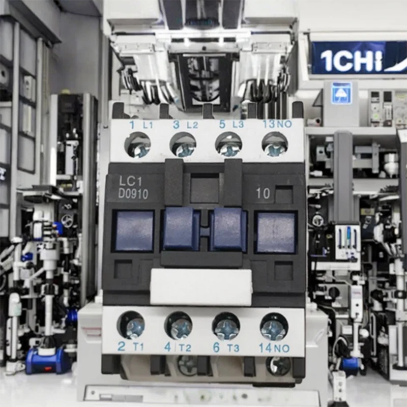
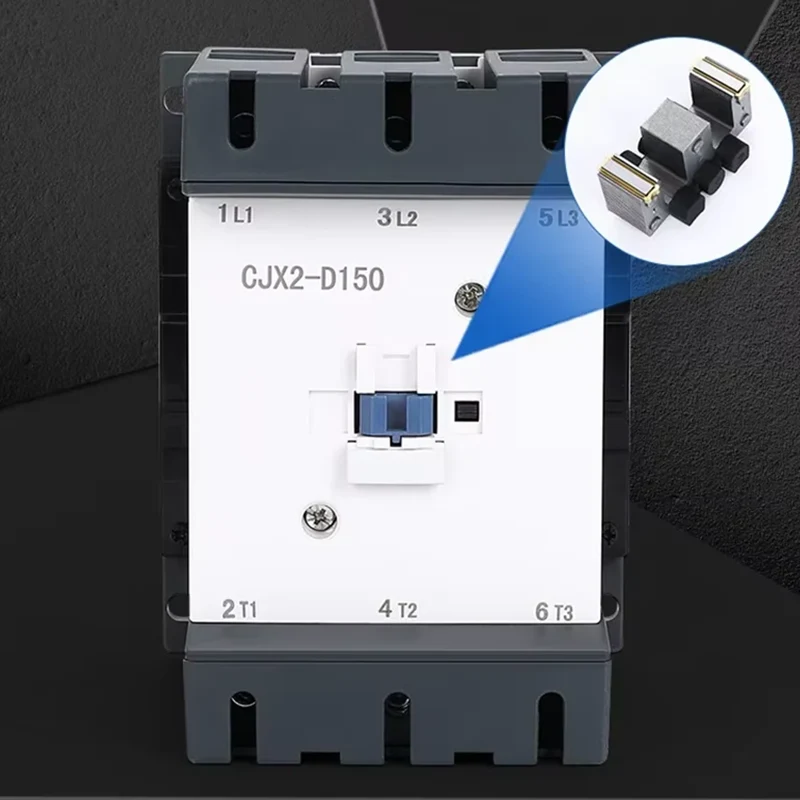
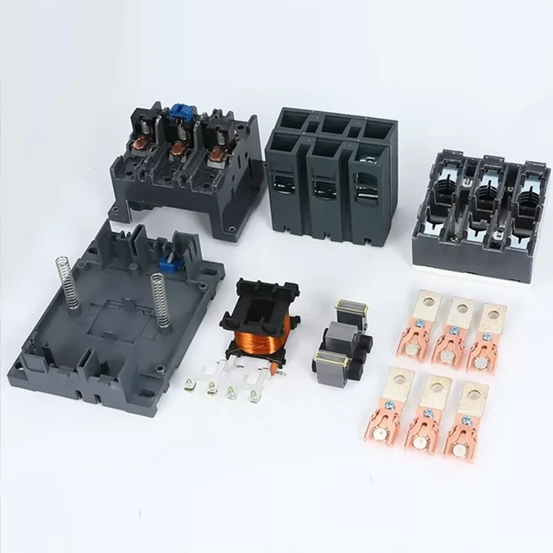
The wiring of AC contactors follows the basic idea of starting with the main circuit and then the control circuit. Depending on the coil voltage and control requirements, the wiring method may vary slightly. The specific steps are as follows:
Understand the core wiring terminals
After receiving the contactor, first confirm the identification:
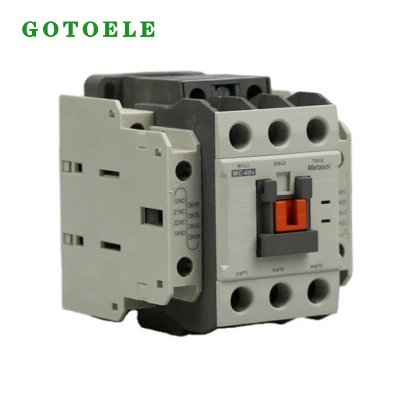
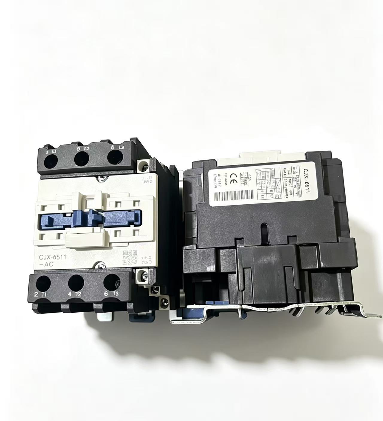
Coil terminals: marked as A1 and A2 (usually there are two interconnected A2 terminals for easy wiring);
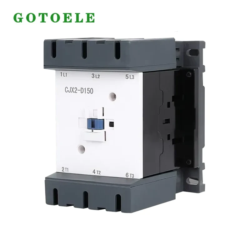
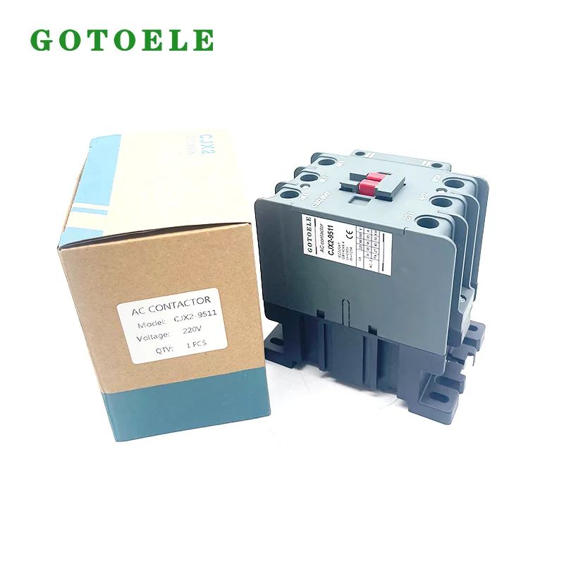
Main circuit terminals: The upper ends L1, L2, and L3 are the incoming terminals, and the lower ends T1, T2, and T3 are the outgoing terminals, connected to the load;
Auxiliary contacts: 13NO/14NO are normally open contacts (disconnected when the coil is not powered), 21NC/22NC are normally closed contacts (closed when the coil is not powered), used for control logic such as self-locking and interlocking.
Basic wiring steps (differentiated by coil voltage)
1. 220V coil contactor
Coil wiring: A1 to neutral wire, A2 to live wire (via control switch);
Main circuit wiring: The upper ends L1 and L2 are connected to neutral and live wires respectively, while the lower ends T1 and T2 are directly connected to 220V electrical equipment;
Work logic: After the coil is powered on, the contactor is closed, the main circuit is connected, and the equipment is started; After a power outage, the main circuit is disconnected and the equipment stops.
2. 380V coil contactor
Coil wiring: A1 and A2 are each connected to a live wire;
Main circuit wiring: Three live wires are connected to the upper ends L1, L2, and L3 respectively, and the lower ends T1, T2, and T3 are directly connected to 380V electrical equipment (commonly three-phase motors);
Work logic: Consistent with 220V, the main circuit is connected after the coil is closed.
Common wiring methods for control scenarios
1. The simplest jog control
Live wire → control button → contactor coil A2, A1 connected to neutral wire/another live wire, the main circuit can be directly connected to the load;
Features: Pressing and holding the button to operate the device, releasing it to stop, is the most basic control method.
2. Common start stop self-protection (start stop) control
The stop button is connected in series to the coil circuit, and the start button is connected in parallel to the normally open auxiliary contact of the contactor;
Logic: After pressing the start button, the coil is powered on, and the normally open auxiliary contact is closed. After releasing the button, the coil can still be continuously powered through the closed auxiliary contact to maintain operation; Press the stop button to power off the coil and stop the device.
3. Motor forward and reverse rotation (double interlock) control
Two contactors are required to connect the normally closed auxiliary contacts of the two contactors in series with each other's coil circuits (to achieve contactor interlocking), and the buttons are also connected in an interlocking form;
Characteristic: Ensure that only one contactor is engaged at the same time to avoid two-phase short circuits, which is the standard connection method for controlling the forward and reverse rotation of the motor.
Remote control
Wiring technique: Connect all stop buttons in series and all start buttons in parallel to achieve control of the same device from multiple locations.
We use cookies to offer you a better browsing experience, analyze site traffic and personalize content. By using this site, you agree to our use of cookies. Privacy Policy